Procedural rigging overview
The Setup Files:
Just a note about rigging in general. When setting-up a rig, it’s always a good idea to give the animators as much freedom as possible in terms of clicking and rotating/translating stuff. It’s probably easier, as a TD, to simply drive things through attributes controlled from the channel box, but usually animators like to just click and go to town with the manipulators.
For the purpose of this quick overview, I’ll use my robot character. This rig-building process requires several different files and can be broadly described as follows:
1) SKELETON:
The first file is the skeleton.ma file. This file actually includes only half of the skeleton. It is used to position the joints where they should be (in regard of the model). The joints will be mirrored to form the final skeleton. The important thing to keep in mind is that the arm plane and leg plane have to be perfectly planar (no deviation or twisting). This can be achieved simply by drawing the joints from front or profile view, and then carefully rotating the joints.
After the joints are created, you can rotate and scale them to get what you need; Be careful with translations, they can get the axis out of whack).
As far as the default pose, I chose to give the arms a 45 degree angle (sort-of half-way between raised and lowered). I usually do not use the “cross” position because I want the scapula and shoulders controls to be at zero rotation by default; In animation, if you get the arms up this way, you have to also rotate the clavicle for it to look correct. Anyway it is really up to you to see what you need.

2) CONTROLS:
Then we have the controls.ma file. This is where you keep your “icons” or “controls”, which are the nurbs curves that the animator will click on to select the joints. They are positioned to be accessible and not to overlap each-other.
During the process, they will be shape-parented to the joints; It means that when you click on the Nurbs control, you actually select the joint itself. This is done using small scripts that will automatize the process (which you can find on the Mel Scripts page).

3) GEOMETRY:
Then of course we have the geometry.ma file, which includes the nurbs/poly/subd surfaces that will get bound to the joints. They are organized in a hierarchy that makes sense and facilitate the binding stage.
Since I tend to use polygons more and more these days, I leave the geometry file in low-rez. Then when binding it, I run a smooth action and put a “smooth level” attribute on the very top node that is connected to all the smooth nodes (as a quick way to control the global level of subdivisions).

Assembled Rig (Without Geometry):
Here, the skeleton has been mirrored, and the controls imported and combined with the skeleton through the rig-building procedure.
As you can see, we end up with a complete rig awaiting for the geometry to be imported and bound. At this point, you can literally animate the rig, as not much will change throughout the later steps.

Final Rig:
This is the final rig. The geometry has been imported and bound to the skeleton.
Now I have to say that I am pretty lazy when it comes to skinning, and I will try as much as possible to have “rigid” parts in my characters (parts that require minimal deformation). Of course in this case it is pretty easy since it is a machine, but you would be surprised by how much you can get away with… The only smooth skinning is on the hinges (the black parts).

The Setup MEL Scripts:
The Maya files we talked-about are really the indispensable “building blocks” of the rig. But now we need to use a whole different batch of MEL scripts to tie them together. They are (again in the case of my robot character):
- buildRobot: Imports the skeleton, mirrors it, do the IK/FK and break rotations setup and imports the controls.
- buildFoot: builds a standard foot rig with “intelligent” toe control, ground height and seamless IK/FK integration.
- bindRobot: All the info about binding the geometry to the joints (whether by skinning or parenting).
- lockHideRobot: Locks and hides all the attributes that shouldn’t be animated.
- robotSetup: A simple interface with buttons that call the setup scripts (each step separately, or all together).
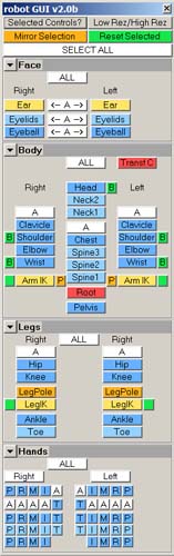
- robotGUI: The GUI to select parts of the character, as well as to switch from IK to FK, and break the rotations…
As a side note, after the binding process, the saved weights for the specific geometry parts are automatically applied, using the weightTools script. It’s a pretty useful thing, as you can point to different folders with different versions of the weights. As long as the names stay the same, the weights will be applied to their corresponding geometry, in effect automatizing the whole process. And if a joint name changes, you just have to edit the weights text file and copy/paste.
At the end of the global build process, an extra “build info” attribute is added on the top node (next to the “smooth level”) to store the date and time of the build (useful in case of referencing).
GUI vs CONTROLS:
GUI (Graphical User Interface) vs Controls (Nurbs curves)? Well, sorry there’s just no “versus” at all; We all require different ways to interact with the rigs at different times. If you plainly see what you want to select, you might just want to click on it. But if you’re far away from the character, or let’s say you want to select the index of the left hand, which is bunched-up in a fist, it’ll be easier to click on the GUI. So, there you go.
Controls and GUI are both indispensable. You can’t entirely forsake one for the other.
That’s it for the breakdown of the different files needed to build the rig. Next part will deal more in details with the way things work. Till then…
A big thank you to Jason Shleiffer, Rick Grandy, Martin Costello, Mike Ulner and the great Character TDs with whom I’ve worked!